Visualizzazione post con etichetta attiny84a. Mostra tutti i post

venerdì 20 ottobre 2017

Keychainino — a modern keychain for maker


Introduction

In this post I describe and show how to assemble the keychianino: a keychain for maker and tech enthusiast
It is quite some time I am following the keychainino project on facebook , and I really love it. It is a small keychain full of technology and most of all is fully ptogrammable.


As described by its author: “keychainino is an arduino programmable keychain”, “is a vintage videogame to be used on the bus, on the metro or anytime one is bored and doesn’t know how to spend the time” :)

Assembling

Below the video of the assembling that I have done


Unboxing

Few days ago I have ordered my keychainino from here [http://www.keychainino.com/product/tht/] and now I got it.


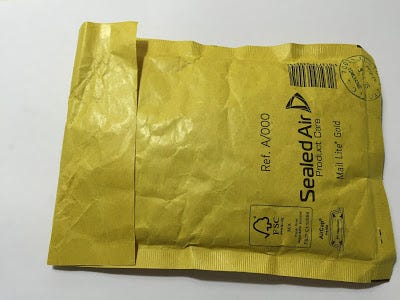
Once I have opened the envelop I found a CR2032 battery and a small antistatic bag containing all the necessary components for the assembly of keychainino (PCB, micro controller, led, resistor)
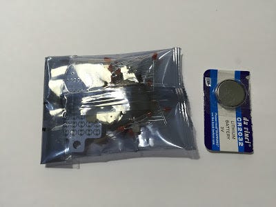


Bill of Material


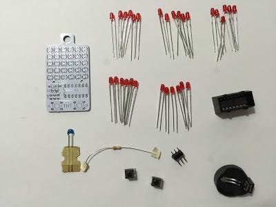
Below the full list of components part of the kit:
  • Keychianino PCB
  • 30 red Led 
  • 1 100nF Capacitor
  • 1 10 KOhm Resistor
  • 1 CR2032 battery holder
  • 1 CR2032 battery
  • 2 micro push buttons
  • 1 ATTINY84A microcontroller
  • 1 ISP pin header (6 pin)


Assembly tips

Before starting the assembly of the PCB and components let me just share few tips:
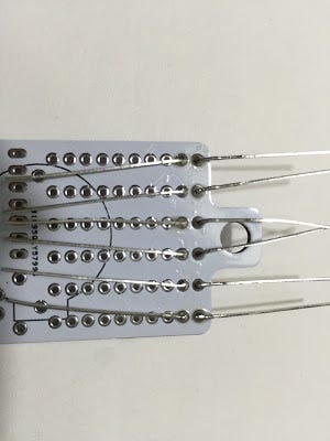
  1. Led are polarized components so it is very important to mount them in the right manner (otherwise keychainino will not work properly). The longer led leg is the anode (positive +) while the shorter one is the cathode (negative -)


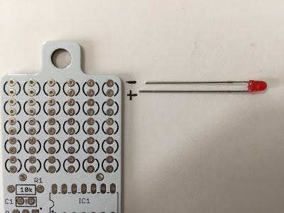
As shown in the above figure, for each led there are two holes in the PCB. The upper hole is for the cathode (negative -) of the led, while the lower hole is for the anode (positive +) of the led.

2. Base don the design of the PCB, the micro push button must be soldered in one specific position.


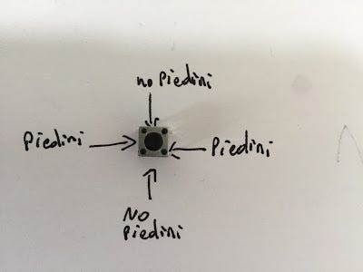
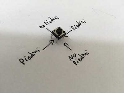
In the above picture, “piedini” stands for “pin”.
So if you look at the micro push button from the top, it must be positioned in a way that pins goes from left to right (not from top to bottom).

3. Also the micro controller ATTINY84A must be mounted in a specific position


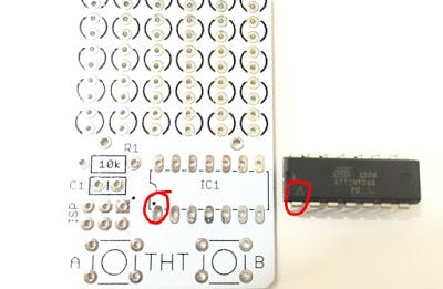
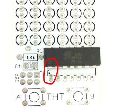
Looking at the PCB from the top, you can see a space named IC1 which is reserved for the micro controller. The bottom-left pad is marked with a tiny black dot.

In the same way if you look the micro controller from the top, you can see a white triangle

The right alignment of the micro controller on the PCB is when the white triangle is matching the tiny black dot as shown in the above picture


Assembly

Now that we know those important tips, we can move on with the assembly of keichainino. Suggest to follow this order:
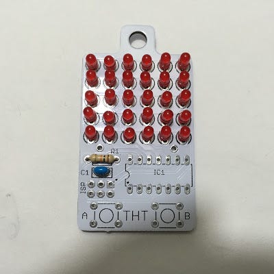
Led


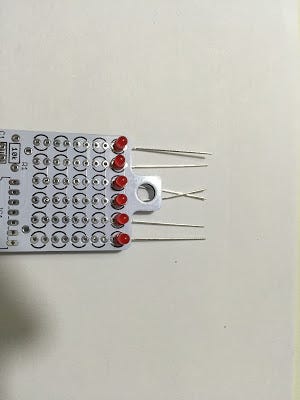
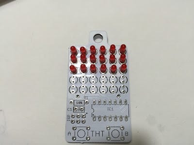
Insert 6 led in the first row of holes from the top. Important to respect the polarization as explained above


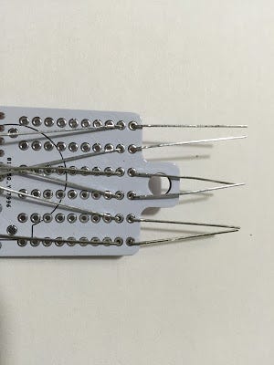
A good way to avoid the led moving is to bend its legs as shown in figure


Now that the led are correctly positioned, we can solder each pin of each led


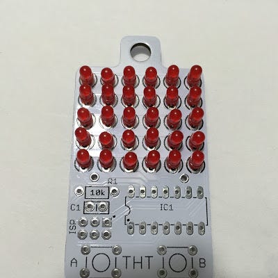
Let’s continue soldering all the led until the last row


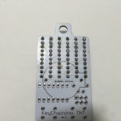
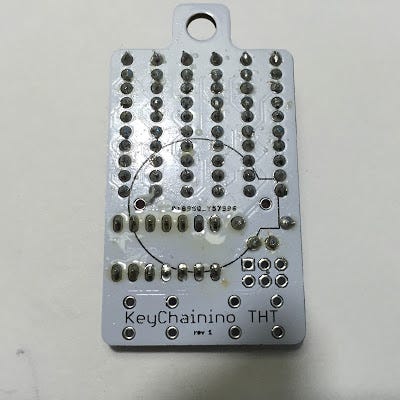
Now all the 60 solders of the led are done (I am sure you can solder much better than me) :) — in the end I am a software guy so I am excused :)


Resistors

Resistors don’t have polariti so it can be soldered in any direction

Capacitor

This is a ceramic capacitor and it doesn’t have any polarity, so feel free to solder it in any direction
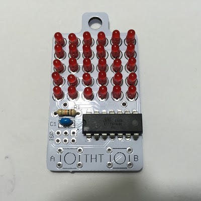


Micro Controller

In order to solder the micro controller I have used a more powerful solder (40W) compared to the one used for the LED (this might be or not your case)
Remember to respect the proper alignment of the micro controller chip as explained above


Micro Push Buttons

Remember to solder the push buttons in the right direction as explained above


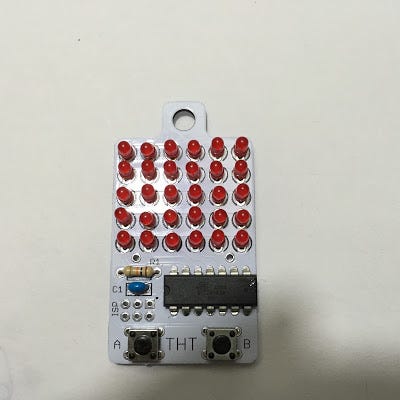
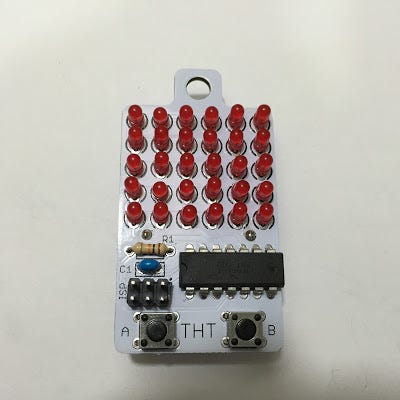
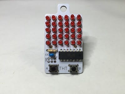
Battery Holder and ISP connector


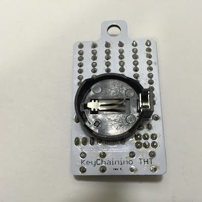
In the end our keychainino is fully assembled and ready for gaming!! :)


domenica 17 aprile 2016

Keychainino - un portachiavi ma non solo - Assemblaggio

In questo posto spiego come assemblare  keychianino.

La guida ufficiale in Inglese e' qui [http://www.keychainino.com/how-to-solder-tht/]


Introduzione


Da qualche tempo seguo su Facebook il progetto keychainino [http://www.keychainino.com/ e https://www.facebook.com/keychainino]


Come definito dal suo autore, keychainino e' "Il primo portachiavi programmabile con arduino", e' un videogioco "vintage"  da usare sull'autobus, sulla metro o comunque quando si e' annoiati e non si sa come passare il tempo :)


Montaggio


Ecco qui il video accelerato del montaggio. Al fondo dell'articolo il video integrale


Ordine

Alcuni giorni fa' ho ordinato il mio keychianino qui [http://www.keychainino.com/product/tht/] ed oggi finalmente e' arrivato a casa tramite una raccomandata postale.


Unboxing

Ecco la piccola busta imbottita a bolle d'aria come ricevuta dal postino


Aprendo il pacchetto, ho trovato al suo interno una batteria di tipo CR2032 ed una bustina contenente tutti i componenti (PCB, microcontrollore e componenti passivi) per assemblare il keychianino


Bill of Material


Ecco la lista dei componenti che ho ricevuto nel kit:


  • Keychianino PCB
  • 30 Led rossi 
  • 1 Condensatore da 100nF
  • 1 Resistenza da 10 KOhm
  • 1 porta batteria CR2032
  • 1 batteria CR2032
  • 2 micro pulsanti
  • 1 microcontrollore ATTINY84A
  • 1 pin header (6 pin) per connettore ISP


Precauzioni per il montaggio

Prima di passare all'assemblaggio e' importante notare un paio di accorgimenti:


Verso montaggio led

I led sono componenti polarizzati e quindi bisogna montarli nel verso corretto altrimento keychianino non funzionera'.

Il piedino del led piu' lungo e' l'anodo (positivo +) mentre il piedino piu' corto e' il catodo (negativo -)


Come indicato nell'immagine, per ogni led da montare sul PCB ci sono due fori.
Qullo piu' in alto coincide con il piedino negativo (catodo) del led, mentre quello piu' in basso coincide con il pidino positivo (anodo) del led


Verso montaggio micropulsanti

In base a come e' progettato il circuito di keychianino i micropulsanti vanno saldati in una specifica posizione


Quindi se osservate il micropulsante dall'alto va orientato in modo che i piedini siano orientati a coppie in verticale verso sinistra e verso destra, mentre nel lato superiore e inferiore del micropulsante non ci devono essere piedini


Verso montaggio ATTINY84A

Anche il microcontrollore ATTINY84A deve essere montato in uno specifico verso


Guardando il PCB di Keychianino dall'alto si vede che nello spazio indicato con IC1 la piazzola in basso a sinistra e' indicata con un puntino nero.
In modo simile guardanto il microcontrollore dall'alto si vede che il pin in basso a sinistra e' indicato con un triangolo bianco.

Possiamo usare questi due segni per capire il verso di montaggio del microcontrollore ATTINY84A. Basta far combaciare il trinangolo bianco con il puntino nero sul PCB

Montaggio

Ora che siamo al corrente di questi piccoli accorgimenti possiamo passare al montaggio di tutti i componenti sul PCB di keychianino seguendo quest'ordine:

  • Led


Inseriamo 6 led nella prima riga in alto rispettando la polarita' come spiegato sopra


Un buon metodo per tenere i led fermi e' quello di piegare il loro piedini come indicato nella figura sopra


Adesso facciamo le saldature piedino per piedino facendo attenzione a non depositare troppo stagno (soprattutto nelle ultime 3 righe di led)


Continuiamo a saldare tutti i led riga per riga fino alla fine


Ed ecco le 60 saldature fatte (sono sicuro che sara' facilissimo fare delle saldature migliori delle mie :) --- ma in fondo sono un softwarista e non un elettrronico)


Ed ecco come appare keychianino dopo aver saldato i 30 led 


  • Resistenza
Come tutti sappiamo la resistenza non ha polarita' quindi puo' essere saldata in qualsiasi verso


  • Condensatore
Questo tipo di condensatore (ceramico) non ha polarita' quindi puo' essere saldato in qualsiasi verso


  • Microcontrollore

Per saldare il microcontrollore io ho dovuto usare un saldatore leggermente piu' potente (40W) rispetto a quello che usato per gli altri componenti 


  • Micropulsanti

Ricordatevi di saldarli con i piedini nel verso giusto come indicato sopra


  • Pin per connessione ISP
  • Portabatteria


Ed infine ecco Keychianino completamente assemblato


Video Integrale del Montaggio