Chi mi segue e conosce sa che non sono un supporter dell'implementazione di un Web Server su un modulo IoT come ESP8266. Fondamentalmente e' per ragioni architetturali che non discuto qui.
Tuttavia nei giorni passati ho ricevuto alcune richieste da utenti che inizia a cimentarsi con ESP8266 sul come realizzare un Web Server con ESP8266.
Ritengo che dato l'uso tipico di un dispositivo come ESP8266 nei progetti sia più' appropriato far vedere come si implementa un semplice HTTP REST server in modo da poter gestire delle risorse.
In questo articolo faccio vedere come gestire 1 Led tramite un API REST con ESP8266.
Circuito di Prova
Il circuito di prova e' banale e raffigurato qui sotto
Per fare il test uso il comando curl da linea di comando (per chi preferisce un client grafico puo' usare l'ottimo postman)
GET ROOT
il primo comando che eseguo e' un HTTP GET della root del server
L'indirizzo IP sara' certamente diverso nella vostra rete e quindi dovete sostituirlo con il vostro (viene stampato sul monitor seriale al boot del ESP8266)
Come si vede ci viene restituita la stringa definita nel codice nella linea 118
GET leds
Adesso interrogo la mia risorsa chiamata leds tramite una HTTP GET
Come si vede mi viene restituito uno stato uguale a 204 indicando che la risorsa non e' disponibile.
POST leds
Adesso creo la risorsa leds fornendo nel body del HTTP POST un json che contiene i seguenti attributi:
id: un numero identificastivo univoco
gpio: il numero di GPIO su cui la mia risorsa (led) e' collegato
status: lo stato della risorsa (0 o LOW)
Come si vede il server mi risponde con un codice 201 indicandomi che la mia risorsa e' stata creata correttamente.
Ora se invio nuovamente un GET sulla risorsa il server mi risponde con 200 e mi fornisce come risposta il JSON che rappresenta la risorsa
PUT leds
Ora che la risorsa esiste posso modificarla con un HTTP PUT.
Anche in questo caso nel body della richiesta inserisco un JSON in cui imposto status a 1 (HIGH)
il server mi risponde con 200 indicando che l'update della risorsa e' andato a buon fine e come si vede sotto il led si accende e rimane acceso.
Analogamente se invio un update con status = 0
il led si spegne e rimane spento.
Nel codice di esempio ho anche gestito altri casi.
Per esempio se faccio l'update (PUT) di una risorsa con id = 2
ottengo un 404 indicandomi che tale risorsa non esiste.
Lascio al lettore l'implementazione del metodo DELETE.
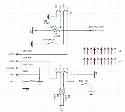
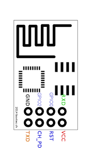
The pinheader J1 and J2, in the above electrical schema, are the 8 pin of the ESP8266–01 module (as seen from above view)
The 5 pin on the left, in the above electrical schema, are the pin of the dev board. More in detail:
VCC: 3V3 (+) from a couple of AA batteries or any other power source (in the schema is writte 5V as I was not able to change it in Fritzing)
GND: the negative (-) wire from the two AA batteries or from any DC 3V3 power source
USB GND: the ground from the USB2TTL module
USB RX/TX: RX/TX from the USB2TTL module
The two pin top-right are the GPIO0 and PIO2 available on the ESP8266–10 module
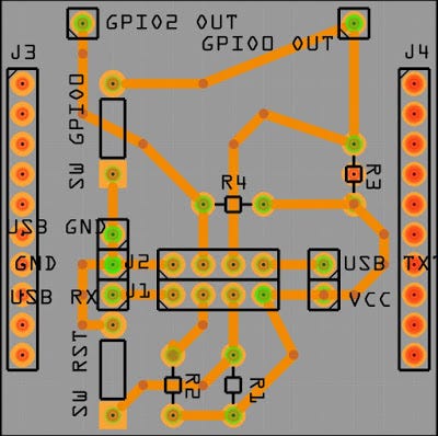
The pin header J3 and J4 are not electrically connected and wired and are only used to mount the dev board on the breadboard
Two micro-buttons are available to reset the ESP8266–01 module (SW RST) and to switch into flashing/programming mode (SW GPIO0)
PCB
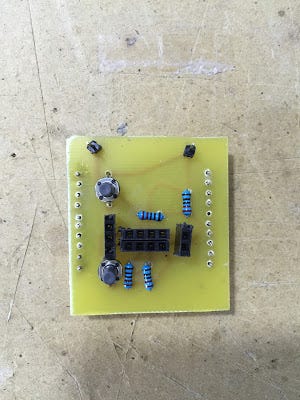
The PCB has been made using Fritzing software and is a single side PCB for an easy development at home
Making the PCB
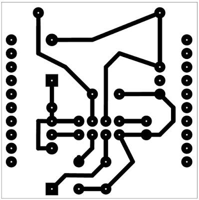
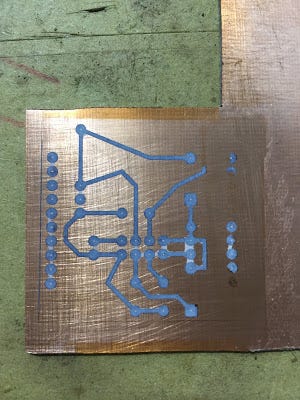
I have use a home made development process to build the PCB which is called “toner transfer”. In short I have printed the circuit on glossy photo paper with a laser printer and later transferred the PCB tracks on the copper clad with a normal iron (borrowed from my wife :) )
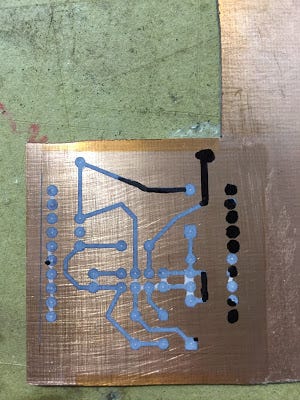
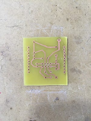
The result is not 100% perfect (doing that at home with basic tools) as half track and few pad have not been transferred correctly
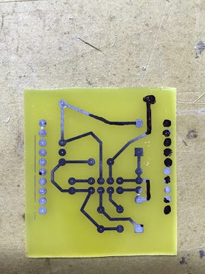
No worries, we are maker so we always find a solution. I have manually corrected the missing toner with a permanent maker (the pad which are missing are the one which are not electrically connected so no big issue)
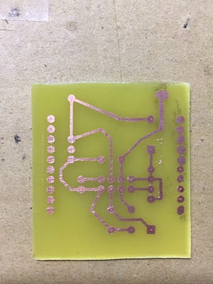
Below the final result after the copper etching
Now I remove the toner with some simple acetone (borrowed from my wife)
now I drill the board with a 1mm drill bit
Assembling the Board
Now it is time to assemble the board with just few components
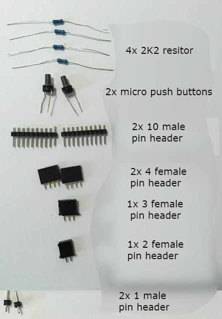
Here the list of components:
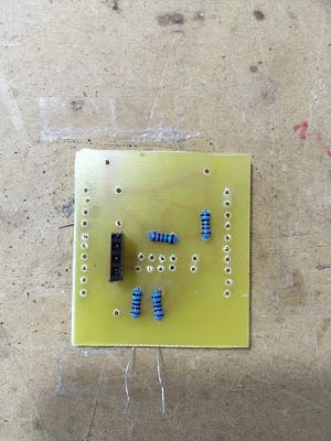
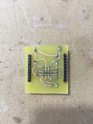
I start by soldering the resistors, the pin header and then the push buttons
Below the final result
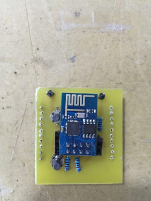
and also with ESP8266–01 module
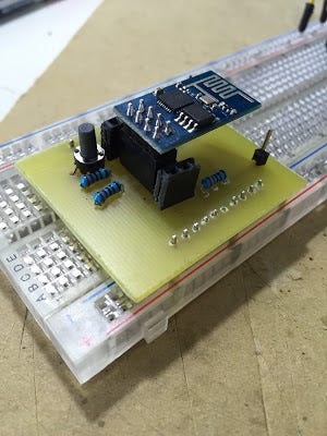
and everything mounted on breadboard
File
The full fritzing project with electrical schema and PCB layout is available here qui
Suggestion
The two pin header rows on the side of the dev board, are slightly larger than the breadboard. In order to overcame this small issue I have removed the 6th pin from the row.
In version 2 of this board I will fix this bug but until then I can use the dev board with the small trick explained above.
This allows me to work on my project base don ESP8266–01 in a clean and easy way avoiding flying wires.
Recently many people asked my help in the implementation of ESP8266 sketches to let two or more modules communicate over the MQTT protocol.
This article provides and describes a basic MQTT source code working skeleton to interconnect ESP8266 modules over MQTT protocol.
The goal of this code is to provide a start point to beginner developers to develop their application by extending it.
MQTT
The main site for MQTT (Message Queuing Telemetry Transport) is [http://mqtt.org/].
MQTT is define in this way: “MQTT is a machine-to-machine (M2M)/”Internet of Things” connectivity protocol. It was designed as an extremely lightweight publish/subscribe messaging transport.”
A communicationBroker : a central communication component which orchestrates all the communication processes and that manages the entire life-cycle of topics and messages
An agent which take the role ofPublisher: sending messages to a specific topic living within a given MQTT
An agent which take the role of Subscriber: receiving messages from a specific topic on a broker
ATopic: a dedicated communication channels between devices
In this architecture a Publisher communicates with one or more Subscriber without knowing its/their identity (any type of addressing)
In other words when a Publisher wants to communicate, it just sends a message to a broker for a specific topic.
After the message has been delivered to the broker, it’s broker responsibility to propagate the message to all the Subscriber which are “listening” of a given topic (Publisher and Subscriber must publish and listen on the same topic).
Such architecture is present in many different IT domains and it is not limited to MQTT only.
As an example (over simplified), the Pub/Sub architecture is used by most of the GUI systems (Windows, Linux, …). For instance when I click on a button in a window, the windows manager send a message (Publisher). The handler of the button is listening (Subscriber) and when receiving a message from the manager it execute a specific piece of code (i.e. close the window)
ESP and MQTT
The MQTT protocol and its Pub/Sub architecture perfectly fits in the communication between ESP8266 devices and between ESP8266 and the external world (cloud). This provides a very easy, lightweight and fast communication mechanism to be used in ESP8266 projects.
A huge advantage, from a networking and security point of view, is that a given ESP can communicates with external devices with no necessity to open a TCP port in the router/firewall (if you implement a more traditional web model yo must open a port in your firewall to accept incoming web requests).
The MQTT protocol is supported by virtually any platform out there and for sure by Android, iOS, Javascript. This allow for an easy communication between a mobile/web application and an ESP module.
CLOUDMQTT
The MQTT broker I typically use for my projects and in this sketch is provided by https://www.cloudmqtt.com/
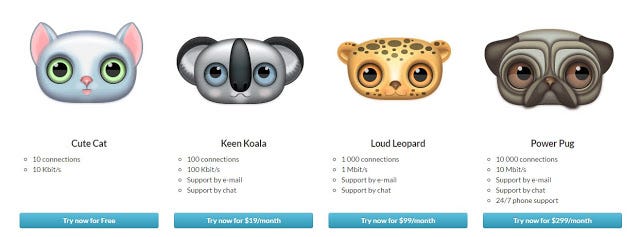
The cloud service is available in different pricing tiers, included my preferred one: the free of charge :)
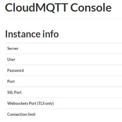
Once you have sign-up to the service you can access the cloud console
Here you can find all the detailed information about your MQTT broker that you can use to configure the ESP sketch
MQTT Basic
The sample code allows one or more ESP to communicate over MQTT protocol and is available here github.
Below some important #define which should be configured before compiling and uploading the sketch to ESP8266
WIFI_SSID: the SSID of your WiFi network
WIFI_PASSWD: WiFi password
MQTT_CLIENT_ID: just a unique (random) ID for your MQTT client
MQTT_SERVER: the FQDN of the MQTT broker
MQTT_UNAME: authentication user name at the broker
MQTT_PASSWD: authentication password at the broker
MQTT_BROKER_PORT: listening broker port
MQTT_TOPIC: the MQTT topic on which exchange messages
The demonstration code can be tested either with 2x ESP communication between each other or 1x ESP and 1x MQTT client (for instance I will show how to use a mosquitto client on Linux, but any other MQTT client will be ok)
ESP as Publisher
On the ESP sketch un-comment #define ESP_PUB_ROLE, then compile and upload the generated binary to ESP
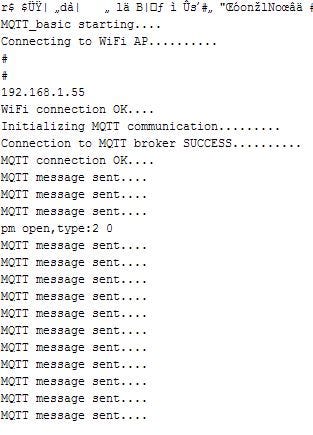
Once the program starts you can see in the serial monitor something similar to the below
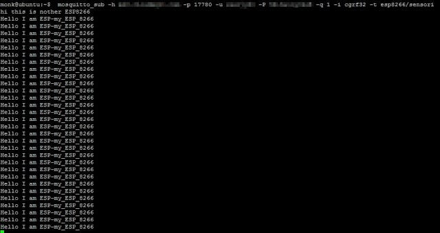
On a Linux shell you need to subscribe to this topic: esp8266/sensori
where the parameters between <> are the one visible in your CloudMQTT cloud console
As you can see from the screenshot, my client running on Linux somewhere in the Internet receives commands (the string “Hello I m ESP-my_ESP_8266”) from my ESP8266 running on my desk in my office. Pretty cool ah!!
ESP as Subscriber
On the ESP sketch un-comment #define ESP_SUB_ROLE, then compile and upload the generated binary to ESP
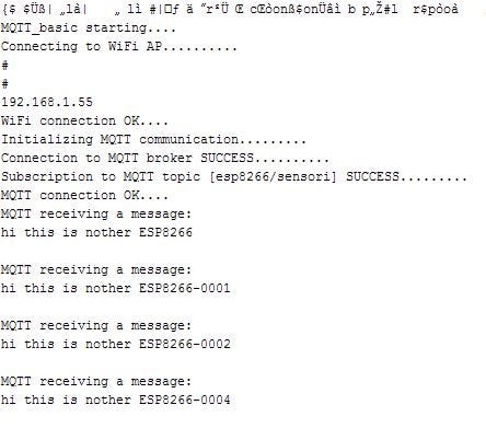
Once the program starts you can see in the serial monitor something similar to the below
On the Linux client now I send commands to my ESP through the following command:
mosquitto_pub -h <host name> -p <port> -u <user name> -p <password> -i <client id univoco> t- esp8266/sensori -m “hi this is another ESP8266”
where the parameters between <> are the one visible in your CloudMQTT cloud console
As you can see from the screenshot, my ESP8266 running on my desk receives commands from my Linux client.
Conclusion
The MQTT protocol and the Pub/Sub architecture are used in different environments and especially in the IoT market. They provide and lightweight and flexible communication mechanism that we can leverage to give our Arduino/ESP projects connectivity to the cloud or local network.
Let me know if you find this short introduction to MQTT on ESP useful and if use it in your projects send me a picture :)