In this post I describe how I connected Arduino Uno (for other Arduino types the wiring are similar) with a JY-MCU HC-06 Bluetooth module I had bought some time ago.
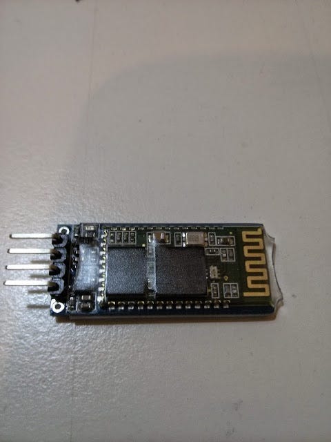
This module allows me to connect via my phone or tablet or PC Bluetooth. The module is seen by Arduino as a serial communication and is therefore easy to manage. I already have a small project in mind for my home with this module, but for the moment, let us concentrate on how to use the module. In order to do it we need to follow the below steps:
- Module configuration
- Using the module
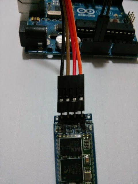
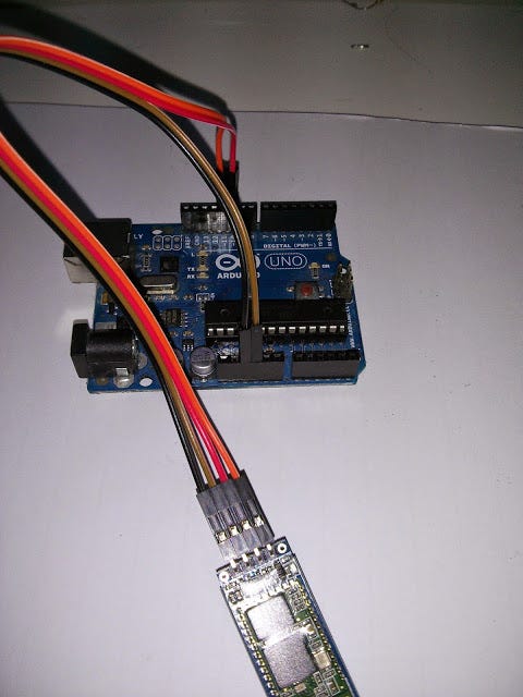
Below a picture showing the wiring between the Bluetooth module and Arduino
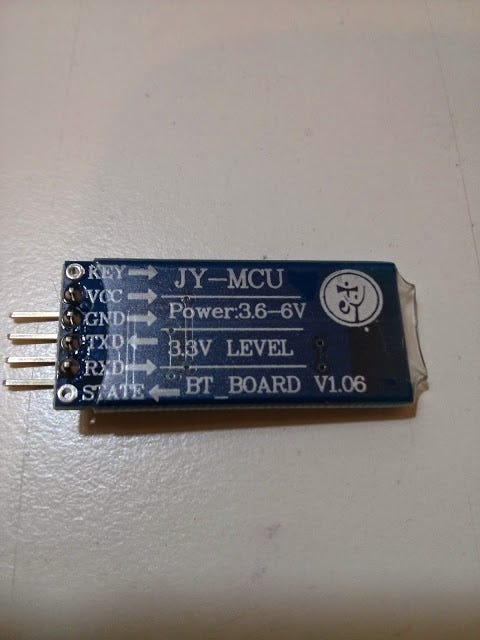
I have used 4 different wires of Black, Brown, Red and Orange color. The wires are connected in the following manner to the Bluetooth module:
- Black -> VCC
- Brown -> GND
- Red -> TX
- Orange -> RX
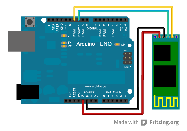
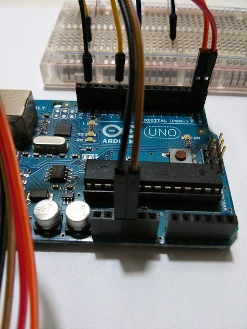
Now let’s connect the other side of the wires to Arduino as in the picture below
- Black -> pin +5V
- Brown-> pin GND
- Red-> pin 10
- Orange-> pin 11
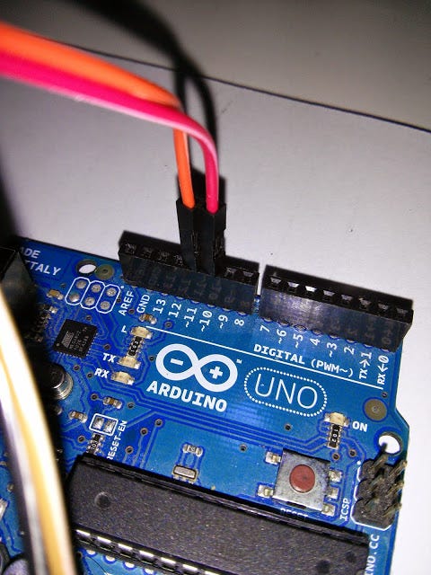
It is important to wire the Bluetooth module to Arduino as described as the configuration software is expecting to have the RX on pin 10 and the TX on pin 11.
So in other words it is a cross connection like this:
- Bluetooth TX → Arduino RX (pin 10)
- Bluetooth RX -> Arduino TX (pin 11)
Once the wiring is completed, load the below sketch to your Arduino:
#define ROBOT_NAME "YOUR ARDUINO NAME"

// If you haven't configured your device before use this
#define BLUETOOTH_SPEED 9600
// If you are modifying your existing configuration, use this:
// #define BLUETOOTH_SPEED 57600

#include <softwareserial.h>

// Swap RX/TX connections on bluetooth chip
//   Pin 10 --> Bluetooth TX
//   Pin 11 --> Bluetooth RX
SoftwareSerial mySerial(10, 11); // RX, TX


/*
  The posible baudrates are:
    AT+BAUD1-------1200
    AT+BAUD2-------2400
    AT+BAUD3-------4800
    AT+BAUD4-------9600 - Default for hc-06
    AT+BAUD5------19200
    AT+BAUD6------38400
    AT+BAUD7------57600 - Johnny-five speed
    AT+BAUD8-----115200
    AT+BAUD9-----230400
    AT+BAUDA-----460800
    AT+BAUDB-----921600
    AT+BAUDC----1382400
*/


void setup()
{
  Serial.begin(9600);
  while (!Serial) {
    ; // wait for serial port to connect. Needed for Leonardo only
  }
  Serial.println("Starting config");
  mySerial.begin(BLUETOOTH_SPEED);
  delay(1000);

  // Should respond with OK
  mySerial.print("AT");
  waitForResponse();

  // Should respond with its version
  mySerial.print("AT+VERSION");
  waitForResponse();

  // Set pin to 0000
  mySerial.print("AT+PIN0000");
  waitForResponse();

  // Set the name to ROBOT_NAME
  mySerial.print("AT+NAME");
  mySerial.print(ROBOT_NAME);
  waitForResponse();

  // Set baudrate to 57600
  mySerial.print("AT+BAUD7");
  waitForResponse();

  Serial.println("Done!");
}

void waitForResponse() {
    delay(1000);
    while (mySerial.available()) {
      Serial.write(mySerial.read());
    }
    Serial.write("\n");
}

void loop() {}
If everything went well you should see in your serial monitor something like the below:
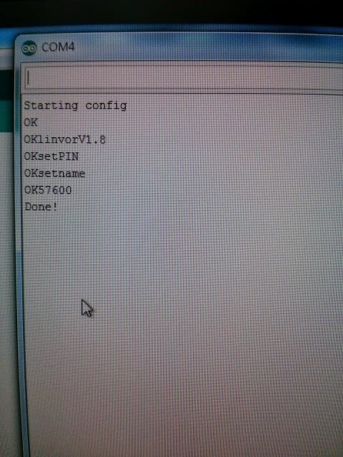
At this stage the Bluetooth module is properly configured and ready to be used for communication with other devices.
The Bluetooth module can be now disconnected from Arduino because we need to connect it slightly differently.
To make sure the module works, I have created a simplest example (see below).
I want to turn ON or turn OFF two LED from my cellphone by sending simple command to Arduino.
I want to turn ON or turn OFF two LED from my cellphone by sending simple command to Arduino.
The commands have the below simple format
# PIN — COMANDO
where
- PIN: pin number on Arduino
- COMANDO: ON or OFF
As an example the following command:
10-ON
sets the pin 10 of Arduino to HIGH
while the command
10-OFF
sets the pin 10 of Arduino to LOW
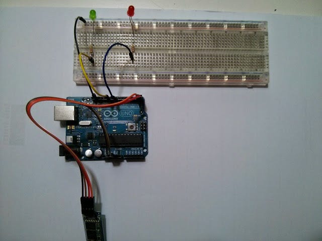
I have created a very simple circuit wiring on breadboard shown below
I have connected pin 8 and 10 of Arduino to two LED through a current limiting resistor (don’t forget to add a 220 Ohm or similar resistor to protect the LED and the Arduino’s GPIOs).
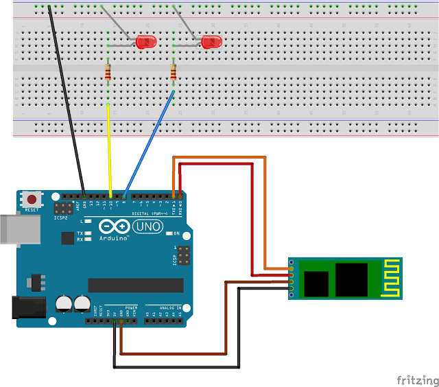
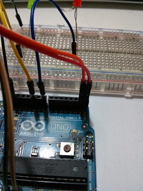
How you can see the JY-MCU Bluetooth module is connected to Arduino in a different way compared to the configuration phase. More in detail now the wiring is:
- Black -> pin +5V
- Brown -> pin GND
- Red-> pin 0 (RX)
- Orange-> pin 1 (TX)
This way the Bluetooth module is seen by Arduino as a serial communication. I have created a simple sketch that is awaiting and executes a command received via Bluetooth protocol.
Obviously, the sketch is quite basic and used just to verify the operation and is not solid enough for a more serious use but should help figure out better how use the module itself.
#include <'string.h>
//struttura del comando
struct CMD {
int pin; //pin da controllare
char *cmd; //comando da applicare al pin (ON|OFF)
};
int i = 0;
int readByte = 0;
char buff[255]; //contiene i dati ricevuti
struct CMD parsed_cmd; //comando ricevuto
void setup()
{
Serial.begin(57600);
bt_println("Init!!!!");
}
//pulisce il buffer dopo che e' stato utilizzato
void clear_buff()
{
for (i=0; i < 255; i++)
buff[i] = 0;
}
//println verso bluetooth
void bt_println(String str)
{
Serial.println(str);
delay(10);
}
//print verso bluetooth
void bt_print(String str)
{
Serial.print(str);
delay(10);
}
//parsing della stringa ricevuta in un comando da eseguire
//comando ha il seguente formato: PIN--COMANDO. esempio: 13--OFF; 13--ON
struct CMD read_command(char *command)
{
struct CMD cmd;
const char s[3] = "--";
char *token;
token = strtok(command, s);
cmd.pin = atoi(token);
token = strtok(NULL, s);
cmd.cmd = token;
return cmd;
}
int validate_cmd(struct CMD cmd)
{
return ((cmd.pin > 0) && ((String(cmd.cmd) == "ON") || (String(cmd.cmd) == "OFF")));
}
void execute_cmd(struct CMD cmd)
{
int pin = cmd.pin;
int status = (String(cmd.cmd) == "ON")?HIGH:LOW;
bt_println(String("Settin PIN: ") + String(pin) + String(" to ") + String(status));
pinMode(pin, OUTPUT);
digitalWrite(pin, status);
}
void loop()
{
clear_buff();
delay(1000);
if ((readByte = Serial.available()) > 0) {
bt_println("-------------------------");
Serial.readBytes(buff, readByte);
bt_println(String("Parsing commnand: ") + buff);
parsed_cmd = read_command(buff);
if (validate_cmd(parsed_cmd)) {
bt_println(String("Serial PIN = ") + String(parsed_cmd.pin));
bt_println(String("Serial STATUS = ") + parsed_cmd.cmd);
execute_cmd(parsed_cmd);
}
else
bt_println("ERROR: COMMAND NOT VALID!");
}
}
Now that we have completed the configuration of the bluetooth module and the wiring of the simple test circuit, we can just load the sketch on Arduino.
To make sure everything works correctly I installed a simple app on my Android phone (for iOS there are similar apps).
The App I have used is called BluetoothTerminal.
This app allows me to type characters (commands) and send them via Bluetooth to my Arduino.
In the video you see that the LEDs turn ON and OFF when I send the correct command to Arduino.
The module I used has a pin equal to 0000 for pairing Bluetooth with the cellphone.
Nessun commento:
Posta un commento